1. General Information
Important
This site is an independent project and is not affiliated with or endorsed by Analog Devices. ADALM-Pluto is a trademark of Analog Devices, Inc
This website aims mainly at providing RF test data for the PLUTO-like SDR platforms based on Zynq FPGA 7010/7020 and AD9363/61 RFIC. I was originally looking at the LibreSDR and I struggled to find anything showing the performance of this device in a controlled environment, therefore decided to do it myself.
This main page will also provide general information few links that I think are useful to know about
1.1. Hardware
There are numerous PLUTO derivatives based on a Zynq FPGA and AD9363. It would be too long to list them all, The picture below shows a few common ones:

Pluto SDR derivativess
1.2. Drivers and Libraries
Windows drivers and Libraries I needed to use the device:
USB driver: https://github.com/analogdevicesinc/plutosdr-m2k-drivers-win/releases
pyadi-iio (Python module for Libiio, necessary if you want to control your device with Python scripts): https://github.com/analogdevicesinc/pyadi-iio?tab=readme-ov-file
1.3. Firmwares
1.3.1. Default firmware
By default the clones ship with an unknown firmware based on the PlutoSDR firmware v0.37 or above, dubbed “v0.xx-dirty”. This “dirty” default firmware seems to be quite limited and not supported so users tend to replace it with an alternative one, the most famous being Tezuka’s (see below)
1.3.2. Alternative firmwares
Most users seem to switch to alternative firmwares. Among the most popular ones:
- Tezuka from F5OEO: https://github.com/F5OEO/tezuka_fw
This firmware is built in many different versions (for different platforms) and adds many new functionalities, as well as support for other open-source projects such as Maia SDR
- libresdr from hz12opensource: https://github.com/hz12opensource/libresdr
This firmware focuses mainly on LibreSDR and overclocking and increasing continuous sampling rate
These two repositories contain convenient SD card images:
Format an SD card in FAT32
Simply extract the content of the release ZIP file onto the SD card
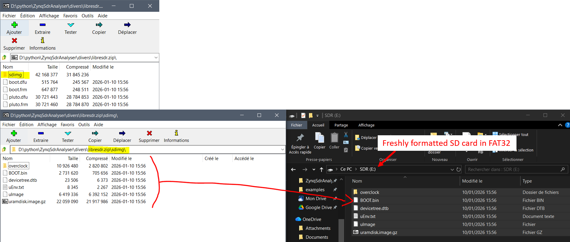
SD card preparation
Insert it in the LibreSDR and plug it in: the SDR will boot from the SD card instead of the internal flash. The device will appear as an external drive (as usual). Open
info.htmland confirm you are running the correct fw (In this example: Tezuka):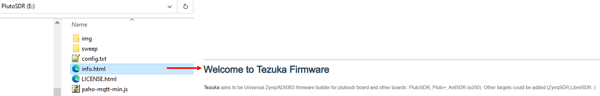
Checking Tezuka has booted
This method has the advantage that the internal flash remains untouched, eliminating the risk of bricking the device.
1.4. Analog devices links
ADALM PLUTO: https://www.analog.com/en/resources/evaluation-hardware-and-software/evaluation-boards-kits/ADALM-PLUTO.html
Pluto Customisation: https://wiki.analog.com/university/tools/pluto/users/customizing
AD9361 IIO driver wiki: https://wiki.analog.com/resources/tools-software/linux-drivers/iio-transceiver/ad9361
1.5. “Extended capabilities”
An AD9363-based device can be set as an AD9364/61 for extended capabilities. The ADI Customization page (see link above) explains the different possible configurations and commands to use. The process is also summarised here.
1.5.1. Configuration
Plug the device to your computer using the USB port. Windows should enumerate a COM port
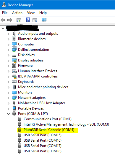
COM port
Connect to that serial port using a tool like TeraTerm or similar with the settings 9600,N,8,1
Connect to the device with username: root and password: analog or password: root (for the “dirty” fw). You will be welcome with a prompt:
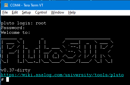
Welcome prompt
Type the following commands:
fw_setenv attr_name compatible
fw_setenv attr_val <rfic>
fw_setenv compatible <rfic>
fw_setenv mode <mode>
reboot
The options for
<rfic>and<mode>are given in the Modes section belowYou can get the current state of the device by typing:
fw_printenv attr_name
fw_printenv attr_val
For example if you get:
fw_printenv attr_name
--> Error: "attr_name" not defined
fw_printenv attr_val
--> Error: "attr_val" not defined
It means those attributes are not defined, the device is therefore in AD9363 mode. This should be the default state.
1.5.2. Available Modes
<rfic> |
<mode> |
LO tuning range |
Max bandwidth |
Max sampling rate |
|---|---|---|---|---|
AD9363 |
1r1t (1x RX + 1x TX) |
325 - 3800 MHz |
20 MHz |
61.44 Msps |
2r2t (2x RX + 2x TX) |
325 - 3800 MHz |
20 MHz |
30.72 Msps |
|
AD9364 |
1r1t (1x RX + 1x TX) |
70 - 6000 MHz |
56 MHz |
61.44 Msps |
AD9361 |
1r1t (1x RX + 1x TX) |
70 - 6000 MHz |
56 MHz |
61.44 Msps |
2r2t (2x RX + 2x TX) |
70 - 6000 MHz |
56 MHz |
30.72 Msps |
Example, to put the device in AD9361 / 2r2t mode, type:
fw_setenv attr_name compatible
fw_setenv attr_val ad9361
fw_setenv compatible ad9361
fw_setenv mode 2r2t
reboot
Warning
While the commands are accepted by my device running the “v0.37-dirty” firmware, the second channels do not seem to work.. it seems to be a firmware issue